SV06 Extruder Disassembly and Assembly Process
1.Remove the silicone cover 2.Unplug the heating line and thermistor line 3. Unscrew the two screws that fix the heating block and remove the hot end 4. Unplug all remaining wiring on the PCB 5. Unscrew the three screws that fix the PCB board and remove the PCB board 6. Unscrew the four small screws that fix the cooling fan and remove the cooling fan 7. Unscrew the two screws that fix the cooling fan bracket and remove the fan bracket 8. Remove the four screws that fix the cooling fan and remove the cooling fan 9. Remove the two screws securing the cooling fan bracket and remove the cooling fan bracket 10. Unscrew the one screw that fixes the proximity switch and remove the proximity switch assembly 11. Unscrew the two screws that fix the proximity switch bracket and remove the proximity switch bracket 12. Unscrew the two screws here, twist slightly, and extrude the shell separately 13. Unscrew the two screws here to disassemble and replace the extrusion motor 14. Take out the planetary gear assembly and remove the extrusion clamp 15. So far, the dismantling step of the nozzle is completed, and the follow-up is the assembly process 16. Install the extrusion clip to the extrusion housing 17. Install the extrusion motor bracket to the extrusion motor 18. Install the planetary gear into the gear groove and check for smooth rotation 19. Buckle the extrusion case and screw the two fixing screws 20. Install the extrusion clamp knob 21. Install the cooling fan bracket 22. The two fans are the same 23. The long screw is installed at the air guide, do not screw it wrong 24. Install the fan using four short screws 25. Install the PCB 26. Install the Proximity Switch Slider Plate 27. Insert the proximity switch assembly slider 28. Tighten the screw, Install the hot end, Tighten the two fixing screws, Assembled model cooling fan bracket 29. Assemble the model cooling fan and air guide 30. Plug in the connecting wires of each component 31. This is a reserved interface, no wiring 32. After installing the silicone cover, the nozzle assembly is completed.
1. Reduce the temperature of the printing nozzle (slowly lower in units of 5C, normally between PLA190C-210C).
2. Adjust the retraction distance and retraction speed of the slicing software (the retraction distance is normally 6mm-10mm, 8mm is recommended; the retraction speed is normally 600mm/s-1000mm/s, and 80mm/s is recommended).
3. The humidity of consumables is too high.
4. The moving distance in the air is too long (an appropriate minimum moving distance can be set, the default is 1.5mm). - The moving distance in the air cannot be changed by the slicer software of Creation.
1. Prepare command (Prepare)
2. Automatically return to the origin (Auto Home)
3. Turn off the stepper drive (wait for the machine to return to the original motion) (Disable Stepper)
1. Use lubricating oil or grease, apply it with a wrench or brush to the two rods of the X axis.
2. Hold the nozzle with your hand and slide it left and right to the maximum position, and slide it several times in the middle.
3. Use lubricating oil or grease, apply it with a wrench or brush to the two rods of the Y axis.
4. Grab the hot bed, slide it back and forth to the maximum position, and slide it several time in the middle.
1.We recommend that you set the printing speed to 50mm/s. If the printing speed is too fast, the quality of the printed model will be affected.
2. Please check the tightness of the X and Y axis timing belts, and adjust it to move smoothly without jamming. You could refer to this timing belt tightness adjustment video: How to adjust the XY axis timing belt | Sovol SV06
3. Please refer to the video, remove the screw rod, and use a ruler to compare with the screw rod . Or you could roll the screw rod on a horizontal table. If it can smoothly roll, it means it is not bent.
If you find that the screw rod is bent and deformed, please contact Sovol customer service and provide pictures or videos of your measurement. Sovol will provide technical support and send the corresponding replacement to you.
Screw rod disassembly reference video: How to replace the screw rod | Sovol SV06
4. Please check the coupling screw that fixes the Z motor axis and screw rod, make sure the screw is tightened, and the Z motor shaft and screw rod are not loose.
Please also check the fixing screw of the screw rod nuts. As long as it can fix the screw rod nuts and not loosen, it does not need to be tightened too tightly.
5. Please check the entire slider position on the nozzle to ensure that there is no up and down, back and forth shaking. And check the fixing screw of the slider on the back plate of the nozzle. As long as it can fix the back plate and not loosen, it does not need to be tightened too tightly.
6. Please refer to the video and lubricate the screw rods , screw rod nuts and smooth shaft guide rail with lubricants, and then print the test file to observe whether the the printing effect has improved.
Test file download link: TBD
lubricant usage tutorial: How to apply lube and replace the bearing | Sovol SV06 Plus
Under what circumstances does Driver error generally appear?
1. First check whether the two ends of the motor wires of X, Y, Z and the extrusion motor are firmly inserted, and whether the wire is damaged?
2. If there is no problem with the motor cable, you can Initialize EEPROM, then restart Auto Home and try again.
3. Move x, y, and z axes independently. If a certain axis fails to move, you can exchange it with other motors on the main board for testing.
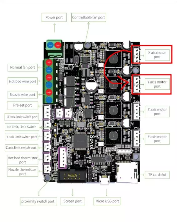
For example, if an error occurs when the X axis is moved alone, you can plug the X motor cable into the Y motor socket on the motherboard (refer to the picture), and then control the Y motor to rotate. In fact, the X motor will rotate.
a. The X-axis motor can rotate normally, and no error is triggered: it means that there is a problem with the main board.
b. The X-axis motor cannot rotate normally, and an error is triggered: it means that there is a problem with the motor line or the motor.
1.Check whether the two ends of the motor wires of X, Y, Z and the extrusion motor are firmly inserted, and whether the wire is damaged?
2. If there is no problem with the motor cable, you can Initialize EEPROM, then restart Auto Home and try again.
3. Move x, y, and z axis independently. If a certain axis fails to move, you can exchange it with other motors on the main board for testing.
For example, if an error occurs when the X axis is moved alone, you can plug the X motor cable into the Y motor socket on the motherboard (refer to the picture), and then control the Y motor to rotate. In fact, the X motor will rotate.
a. The X-axis motor can rotate normally, and no error is triggered: it means that there is a problem with the main board.
b. The X-axis motor cannot rotate normally, and an error is triggered: it means that there is a problem with the motor line or the motor.


